Project 7: Hull Thickness Measurements
Introduction
The most significant threat to the survival of the A7 submarine is corrosion; the submarine has been immersed in seawater for more than 100 years so the strong steel hull is rusting away, slowly turning into structurally much weaker corrosion products. One of the requirements for the A7 Project was that measurements be made of the remaining thickness of metal in the hull plates. This would provide information about the condition of the hull structure and gives some indication of how long the submarine will remain intact on the seabed.
The thickness of metal remaining in the hull plates (strakes) were measured by divers at a number of points on the hull using a Cygnus Instruments DIVE Mk2 underwater digital ultrasonic thickness gauge. The ultrasonic thickness (UT) measurements were compared to the original thickness of the plates when the ship was constructed to give an idea of the degree of corrosion of the hull and an estimate of the rate of corrosion. Subsequent measurements made at a later date can be used to improve this estimate of the rate of corrosion.
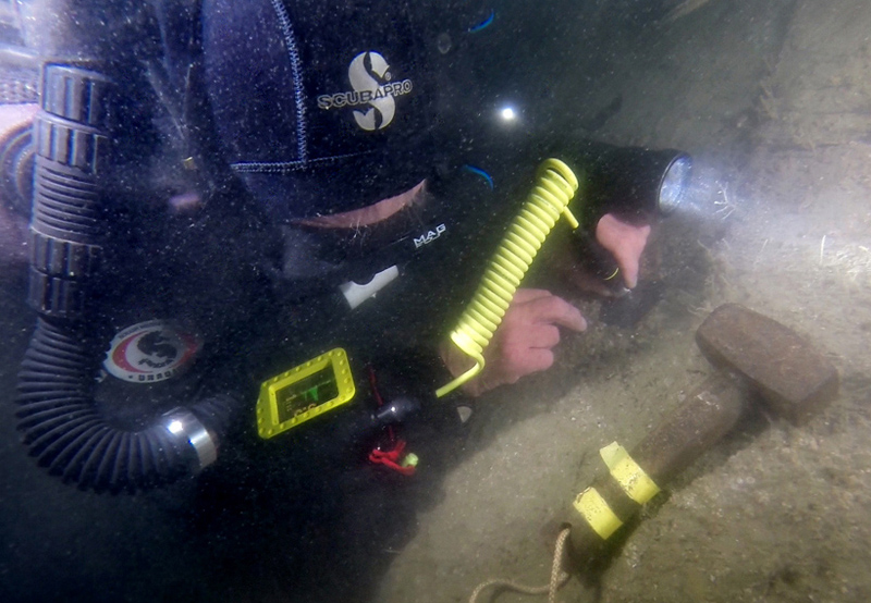
Making hull thickness measurements on submarine A7
Corrosion of Iron and Steel
Iron and steel corrode in seawater forming a hard scale or concretion layer on the metal surface which is made up of iron corrosion products, the remains of marine organisms plus seabed material if the item is close to the bottom. The composition of the concretion can vary considerably as can its hardness and its ability to adhere to the underlying metal. The concretion forms a barrier over the metal which slows the rate of decay by reducing the amount of dissolved oxygen reaching the metal surface, as the concretion forms a protective layer over the bare metal the removal of this layer may increase localised corrosion at that point. Thus any method used to measure hull plate thickness should ideally give minimal disturbance to this layer of concretion, and should include steps to minimise the disturbance if it has to occur. The underlying metal slowly corrodes and is replaced by layers of corrosion products; the corrosion is uneven across the metal plate which gives the metal a rough or pitted surface. Eventually, the corroding metal plate can become so thin that holes form within the plate leaving a lace-like web of metal held together by corrosion products, finally all of the metal corrodes away leaving just the layers of structurally weak corrosion products. At some point in the decay process the structure may become so weak that it cannot support its own weight or any forces acting on it through the effects of tides and storms. At this point the structure collapses, shedding some of the outer concretion layers in the process and exposing what remains of the bare metal to seawater, further accelerating the corrosion. For a detailed discussion about iron corrosion see Pearson, 1987, Conservation of Marine Archaeological Objects, p212.
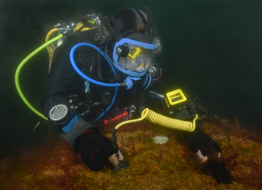
Testing the Cygnus DIVE gauge underwater on a wreck off Plymouth
The Cygnus Instruments DIVE Mk. 2 ultrasonic thickness gauge
An ultrasonic thickness (UT) gauge can be used to measure thickness of metal and many other solid materials. The UT gauge sends short pulses of very high frequency sound waves from a hand-held probe in contact with the hull plating and measures the time taken for each sound pulse to travel through the plate, reflect off the back wall of the material then return to the probe. If the speed of sound in the material being tested is known then it is possible to calculate the thickness of the material by multiplying the speed of sound by half the total travel time.
The instrument chosen for this project was the DIVE Mk2 underwater ultrasonic digital thickness gauge made by Cygnus Instruments Ltd. This instrument is robust, small and lightweight so can be worn on the diver’s wrist. The gauge is automatic in operation so there are no controls to adjust before making a measurement. This is a big advantage when time on site is short and also makes the instrument very easy to use. The gauge can be fitted with different types of probe so we undertook experiments to determine the effectiveness of each type for UCH work. The display shown to the operator is easily understood but provides essential feedback about the quality of the ultrasonic signals being received and the measurements that have been made. An optional upgrade to the basic gauge is the ability to store up to 5000 thickness measurements in its internal memory, arranged in groups selected by the operator. The measurements are automatically logged when a stable measurement is made so the operation is hands-free. Once the measurements have been made and the gauge is back on the surface the logged measurement data can be uploaded in to a computer for display and annotation using the Cygnus Instruments CygLink software supplied with the gauge. Once any annotations have been added the CygLink software can be used to produce a PDF report on the measurements or the measurements can be exported to a spreadsheet.
The Cygnus DIVE Mk2 used on this project is the next generation of the instrument that was used by Wessex Archaeology for hull thickness measurements on submarines Holland No. 5 and HMS/M A1. A Cygnus DIVE gauge was to be loaned to the project by MOD Salvage and Marine Operations; instead sponsorship was obtained through ProMare and Cygnus Instruments to purchase an instrument for the project.
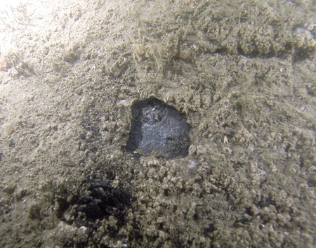
A small area of concretion removed to show the bright but uneven and pitted metal underneath
Method
Although the use of ultrasonic thickness (UT) gauges is commonplace for the inspection ship hulls, pipelines and offshore installations, their use is relatively new in the field of underwater cultural heritage. As such, few experiments have been done in to the use of these instruments on submerged shipwrecks and recommendations for their use are rare. One of the most recent papers to provide recommendations was the 2012 report by Wessex Archaeology ‘Ultrasonic Thickness Measurement Methodology Development and Testing Holland No. 5 and HMS/M A1’ which used many of the previous papers for inspiration, so the Wessex report and an associated paper were used as a starting point for further work.
A series of experiments were undertaken by the project team prior to and during fieldwork to determine the most reliable way to record plate thickness measurements. The experiments showed that the best results would be obtained using the 5 MHz twin crystal probe (Cygnus Type T5B, yellow band) so this is what was used on the A7 hull.
The initial aim was to record measurements at eight locations on the hull. Additional measurements were planned to be made on non-structural elements to provide complementary data from this site to that collected for the First World War Submarine Project run by English Heritage.
The procedure for making UT measurements is given below:
1. Just before diving, 20mm diameter balls of epoxy putty to be used for filling holes in the concretion were mixed together then placed in a plastic bag2. On site, the surface of the metal to measure was prepared by removing the surface concretion with a chisel to leave a clean but pitted surface with an area large enough to admit the UT probe
3. The UT gauge was set to record the next set of measurements in a new logging group
4. The probe was placed on the cleaned area and a minimum of three measurements were made and logged at each location
5. Finally the cavity made in the concretion was filled with epoxy putty
Results
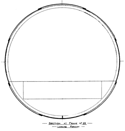
Plate and frame construction diagram showing the arrangement of laps (NMM)
The intention was to record eight measurement points on the hull; however three of the points were not measured due to lack of available time on site. The DIVE gauge was very easy to use as it could be worn on the diver’s wrist leaving the hands free to operate diving equipment during descent and ascent to and from the wreck. Once on site the display was bright, clear and easily understood in low light, poor visibility and under the effects of narcosis. The concretion on the pressure hull of the submarine was quite soft with a texture like biscuit so could be removed easily with a chisel. Under the concretion was a thin, black graphitised layer which was washed or rubbed away leaving bright and shiny metal that was uneven in texture and severely pitted.
Although the DIVE gauge was very easy to use underwater there were a few difficulties in making the measurements. If the diver making the measurements left insufficient time between finishing one measurement and starting another the automatic logging capability in the gauge would not trigger another measurement. This was an operator error rather than a problem with the instrument so changing the operating procedure soon remedied this problem once it had been identified. The uneven and pitted surface of the steel hull made it difficult to hold the probe sufficiently still for a measurement to be made as the probe had to give a reading that varied no more than 0.2mm for 2 seconds. The probe needed to be pressed to the hull quite firmly which was found to be difficult for the normally neutrally buoyant diver as pressing down on the probe just pushed them off the hull. The submarine hull shape made matters worse as being smooth there was little to hold on to and the curve of the circular hull limited measurements to the upper area. Initially we had planned to measure the hull thickness on the centreline of the submarine just below seabed level but this was found to be impossible. The diver could not hold the probe sufficiently still while lying upside down on the hull and avoiding damage to the sea fans found growing there. Working from the seabed was also not possible as the overlying silt was so soft the diver would simply sink into it before a measurement could be made, also reducing visibility to nil instantly.
The circular steel frames used to construct the A class boats were 3½ in. x 3 in. (89 x 76mm) 7.8lb (3/16 in., 5mm) angle spaced 18 in. (458mm) apart.
Eight strakes were used to plate over the frames with 4in. (102mm) laps where two strakes joined. The upper, lower and side plates were 20 lbs (1/2 in., 12.7mm) while the others were thinner at 17½ lb (7/16 in., 11.1mm). Fig. 63 is a cross section of the boat at frame 25 showing a circular frame overlaid with a section through each strake. The arrangement for overlapping each strake is also shown.
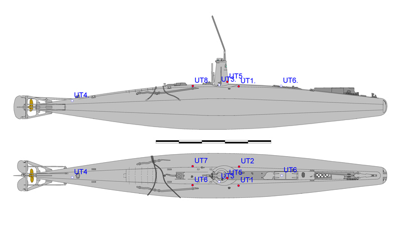
Ultrasonic thickness measurement points on the hull of the A7
Measurements were made at five of the eight points:
Point |
Location |
Value |
Measurements (mm) |
Notes |
UT1 |
Foredeck starboard |
5.1 |
3.4, 5.4, 5.1 |
Poor quality |
UT2 |
Foredeck port |
8.9 |
8.0, 8.9 |
Trace shows first value was short. On strake overlap |
UT3 |
Conning tower fairing |
None |
|
Planned but not completed |
UT4 |
Stern, below mud line |
None |
|
Planned but not completed |
UT5 |
Conning tower, forward |
3.7 |
4.4,3.8, 3.6, 3.8, 3.7, 4.0 |
Some measurements noisy |
UT6 |
Torpedo loading hatch |
None |
|
Planned but not completed |
UT7 |
Aft deck port |
9.6 |
10.1, 9.2, 9.6, 9.6 |
First & second values have indistinct leading edge |
UT8 |
Aft deck starboard |
9.7 |
8.8, 9.7, 9.8 |
First trace is noisy |
Point UT1
Point UT1 was on the starboard side, 1m forward of the conning tower, on the second strake just below the lap where it joins the upper strake, which was originally 11.1mm thick. It was difficult to make measurements at this point and those that were made were poor quality; a number of measurements were attempted on two separate occasions. One measurement of 3.4mm was recorded with the others at 5.4mm and 5.1mm but all were noisy so were less reliable. The location is close to the hole H1 so the hull plating may be particularly thin or pitted in this area.
Point UT2
The measurement was inadvertently made on the overlap between the upper strake (12.7mm) and the second strake (11.1mm) and only discovered after the concretion had been removed. The remaining plating thickness was recorded to be 8.9mm. This measurement is assumed to be from just the upper strake originally 12.7mm thick. At the point where the measurement was made the second strake overlaps the upper strake and provides a barrier to corrosion for the underside of the upper strake, so it is likely that corrosion of the upper strake will be less at this point.
Point UT5
The conning tower in submarine A1 was in the form of a truncated cone of 15 lbs (3/8 in., 9.5mm) steel plating and A7 is thought to have a conning tower made with the same thickness of steel. Point UT5 was on the front face of the conning tower 0.5m above the casing. Six measurements made at this point gave a repeatable thickness of 3.7mm.
Points UT7 and UT8
Points UT7 and UT8 were 2.2m aft of the conning tower and 0.8m off the centreline on the port and starboard sides. The measurements were made on the upper edge of the second strake which was originally 11.1mm thick. The measurement for UT7 (Port) was 9.6mm and for UT8 (Stbd.) it was 9.7mm. This value is considerably thicker than the equivalent measurements made at points forward of the conning tower. It is possible that both measurements were made directly over a frame which may reduce the rate of corrosion on the inner face of the metal.
Material Loss
Point |
Location |
Meas. |
Original (mm) |
Loss (mm) |
UT1 |
Foredeck starboard |
5.1 |
11.1 |
6.0 |
UT2 |
Foredeck port |
8.9 |
12.7 |
3.8 |
UT5 |
Conning tower, forward |
3.7 |
9.5 |
5.8 |
UT7 |
Aft deck port |
9.6 |
11.1 |
1.5 |
UT8 |
Aft deck starboard |
9.7 |
11.1 |
1.4 |
Analysis
The measurements at UT5 on the conning tower were both reliable and repeatable and show a loss of 5.8mm from the steel plating. The estimate of plate thickness lost at UT1 (foredeck starboard) is 6.0mm, this is based on just two measurements so is less reliable, but it does agree with the better quality measurements from the conning tower. The loss of metal at point UT2 (foredeck port) was just 3.8mm but this lower value is probably caused by the protection to the underside of this plate by the overlapping strake underneath. The measurements for UT7 and UT8 are an anomaly as if measured through just the hull plate alone show a metal loss of just 1.5mm.
In conclusion, the most reliable measurement for the loss of hull plate thickness is 5.8mm in 100 years, or a rate of 0.058 mm/year or 58 μm/year. This is a loss of 61% of the original conning tower thickness and 52% of the original hull plate thickness.
Note that the measurements only include the exposed portion of the hull of A7. The portion of the hull in the seabed is likely to be much better preserved as it is buried so may survive for longer within the seabed after the visible part has corroded away.
Comparison with A1
Wessex Archaeology undertook a similar ultrasonic hull thickness survey on submarine A1 in 2012. This is useful for comparison with the results from the A7 UT survey as the boats share the same design for the pressure hull and A1 sank for the final time just 3 years before A7. Three hull thickness measurements were made in total on the hull of A1 but no calculation of metal thickness loss was included in the report. The location of the points where the measurements were is vague but Figure 1 in the report hints that the measurements were made on the thinner second strake (11.1mm) rather than the thicker upper strake. Measurement point TL2 located approximately 1m aft of the bow gave a thickness of 5.6mm which equates to a loss of 5.5mm of steel from that strake. Point TL 5 was located in line with the front of the conning tower and reported a thickness of 5.7mm, which is a loss of 5.4mm in thickness. Little can be concluded from a few measurements taken from uncertain locations on the hull of A1 but it is still interesting to note that these measurements are similar to the 5.8mm of steel plate lost from the hull of A7.
Prediction
A simple projection forward in time with this rate of loss of material gives a prediction that the conning tower will have corroded completely in just 63 years and the pressure hull in 87 years.
However these values are likely to be over-estimates as the corrosion products are considerably weaker than the metal they replace. The strakes are likely to collapse under their own weight before all of the metal corrodes and the frames supporting the hull plating were originally only 5mm thick so there may now be little metal remaining within a shell of concretion. Both of these factors will shorten the predicted survival time for the hull. The corroding steel conning tower holds up the heavy gunmetal cap, hatch and periscope so the weight of this top load is likely to collapse the conning tower before the steel in the tower corrodes completely. The hull of the submarine is almost completely sealed at the moment so water flow inside the hull is minimal but as the hull strakes become thinner they will be perforated by small holes which enlarge over time. As holes develop in the hull plates any tidal currents will start to flow through the hull which will increase erosion, and potentially increase oxygen levels within the hull which will then increase the rate of corrosion.
In conclusion, a conservative estimate for the survival of the visible part of hull of the A7 submarine is 40 to 50 years.

