
The Liberty Ship Engine
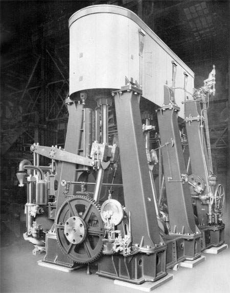
The engine fitted to the James Eagan Layne is an oil fired triple expansion engine weighing 135 tons built by the Joshua Hendy Iron Works in Sunnyvale, California.
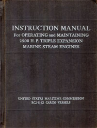
The information below has been taken from the Instruction Manual for Operating and Maintaining 2500 H.P. Triple Expansion Marine Steam Engines, EC2-S-C1 Cargo Vessels, written by the United States Maritime Commission (1).
Description
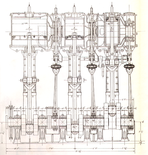
The main engine is of the vertical, 3-cylinder, triple expansion type with the following cylinder dimensions:
24.5-37-70 x 48" stroke, developing 2,500 I. H. P. at 76 R. P. M.
Steam pressure 220 = , maximum steam temperature 450°, 26" vacuum.
The engines are built to the American Bureau of Shipping classification AMS.
The cylinder arrangement from forward to aft is:
High Pressure; Medium Pressure; Low Pressure
The H. P. cylinder is provided with liner for the piston as well as the piston valve.
All cylinders are cast individually and bolted together, forming unit block.
Steam chests are cast integrally with cylinders, thus eliminating interconnecting steam pipes.
The H. P. cylinder is fitted with piston valve, and M. P. and L. P. cylinder with box-type balanced slide valves.
The valves admit steam as follows: H. P. inside steam, M. P. and L. P. outside steam.
Bedplate is continuous under the entire engine and supports the cylinders through columns. The main bearings for supporting the crankshaft are set in recesses in cross girders. The bedplate is bolted directly through chocks to the tank top.
Columns are of the box-type construction; to the back columns are bolted separate crosshead guide plates and back guides. The crosshead guides are water cooled.
Lockwood and Carlisle rings are fitted to the H. P. piston valve and the H. P. and M. P. pistons. L. P. piston has Ramsbottom ring with coach springs.
Metallic packing is used throughout for all piston rods and valve stems.
The direction of rotation of the engine seen from the coupling end is clockwise, with crank sequence as follows: H. P.—L. P.—M. P.
The crankshaft is of the built-up type made in two sections with H. P. and M. P. forming forward section, and L. P. the aft section. The valve gear is of the Stephenson link type. The eccentric rods are crossed and attached to the eccentric straps at the bottom and to the link bars on top.
The reverse shaft is located on the back of the engine and secured to the M. P. and L. P. cylinders and H. P. back column.
The reverse levers are slotted for linking up screws for changing the points of cut-off of individual cylinders
The reversing engine is of the all-around type bolted to the H. P. front column.
The turning engine is attached to the bedplate and used for turning the main engine over when required for repairs or setting valves.
The air pump is of the Edwards type, single-acting, and driven from the L. P. main crosshead through beams connected to the pump crosshead, and is attached to the bedplate and aft LP. column.
Two bilge pumps, one bolted to each side of the air pump, are driven from the air pump beam. The suction and discharge valves are located in manifold valves with safety valves, and connections provided for attaching to the vessel piping.
The evaporator feed pump is attached to the L. P. back column, and driven from the beam through linkage.
The thrust bearing is of the Kingsbury type, and bolted to the tank top independent of the engine bedplate.
The throttle valve is of the single-seated balanced type, operated by handwheel at the starting platform, and with extension above for operation from deck. A special butterfly valve is built into the throttle valve for quick opening and closing, and operated from the starting platform.
The by-pass valve and drain valves are attached to the cylinders, and operated from the starting platform.
Lubrication for running parts is from oil boxes located at the upper end of the cylinder, with pipes leading to boxes on running parts. Separate boxes are located on the eccentric rods for oiling the eccentric straps. Special lubricating boxes are located on the main and air pump beam bearings for the lubrication of same.
Forced feed lubricator is located on H. P. back column, and operated from the crosshead for positive lubrication to throttle valve, M. P. slide valve, and H. P. piston rod packing.
 |
 |
|---|---|
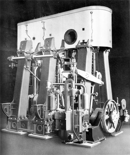
Operating side of the engine |
Exhaust side of the engine |
Sea water cooling is provided for main bearings and eccentrics.
The gauge board is located at the starting platform, and contains the necessary gauges for observing operating conditions of the engine.
Counter is located on the M. P. front column, and driven from the crosshead.
Relief valves are provided on all cylinders and for the M. P. and L. P. valve chest
The cylinders are covered with magnesia protected by sheet-iron lagging.
The top of the engine has a mat covering with sheet iron, and so split that parts can be taken off for removal of the various cylinder and chest covers.
Indicator cocks and gear are provided for all cylinders.
One indicator with springs is furnished for each vessel.
References
(1) USMC, 1942, Instruction Manual for Operating and Maintaining 2500 H.P. Triple Expansion Marine Steam Engines, EC2-S-C1 Cargo Vessels
![]() If you can provide more information about this then please contact us.
If you can provide more information about this then please contact us.
